

Installing graphene underfloor heating transforms your home’s comfort with modern heating technology that’s efficient and space-saving. This comprehensive guide walks homeowners, contractors, and DIY enthusiasts through the complete graphene underfloor heating installation process from start to finish.
Unlike traditional heating systems, graphene heating film systems offer quick installation, minimal floor height requirements, and long-term reliability. You’ll learn the essential pre-installation planning steps, proper graphene heating film setup techniques, and thermostat configuration for optimal performance.
We’ll cover the technical aspects of graphene floor heating system installation, including proper preparation methods and safety protocols. You’ll also discover practical maintenance tips and troubleshooting solutions to keep your electric underfloor heating running smoothly for years to come. Whether you’re upgrading an existing system or installing new radiant floor heating, this step-by-step approach ensures professional results every time.
Understanding Graphene Underfloor Heating Technology
What is graphene heating and how it works
Graphene heating represents a revolutionary advancement in heating technology, utilizing one of the most remarkable materials discovered in modern science. Graphene is a super-thin layer of carbon atoms arranged in a distinctive honeycomb pattern, measuring just one atom thick, making it the thinnest material on Earth. Despite its incredibly thin profile, this wonder material boasts extraordinary properties that make it ideal for graphene underfloor heating installation applications.
The fundamental strength of graphene is truly remarkable – it’s 200 times stronger than steel while maintaining exceptional flexibility. This unique combination allows graphene heating film systems to be incredibly durable yet adaptable to various installation surfaces. The material’s transparency and lightweight nature further enhance its suitability for underfloor heating applications, as it can be seamlessly integrated without adding bulk or weight to flooring systems.
At the core of graphene’s heating capability is its extraordinary electrical and thermal conductivity. When electrical current passes through graphene heating elements, the material converts electricity into heat with exceptional efficiency. Unlike traditional heating methods that rely on convection or conduction through metal elements, graphene heating operates through far-infrared radiation principles, creating a more comfortable and healthy heating experience.
The heating process begins when electricity flows through the graphene film, causing the carbon atoms to vibrate at specific frequencies. This vibration generates far-infrared radiation, which directly heats objects and people in the room rather than just warming the air. This direct heating method is not only more comfortable for occupants but also significantly more energy-efficient than conventional heating systems.
The ultra-efficient heat conductivity of graphene enables heating elements to reach operational temperatures almost instantly. When you activate a graphene floor heating system, the heating response is measured in seconds rather than minutes, providing immediate comfort when needed. This rapid heating capability also means the system uses less energy to reach desired temperatures, contributing to overall energy savings.
Types of graphene underfloor heating systems available
The market for graphene underfloor heating offers several distinct system types, each designed to meet specific installation requirements and performance needs. Understanding these variations is crucial when planning your graphene heating film setup.
Graphene Heating Film Systems represent the most common type available for residential and commercial applications. These ultra-thin films can be installed directly under various flooring materials, including laminate, engineered wood, vinyl, and tile. The film thickness typically ranges from 0.3mm to 0.5mm, making them virtually undetectable once installed. These systems operate at low voltages, typically 12V or 24V, enhancing safety while maintaining excellent heating performance.
Modular Graphene Heating Panels offer increased flexibility for larger installations. These panels can be configured in various sizes and patterns to accommodate different room layouts and heating requirements. The modular design allows for zone-based heating control, enabling users to heat specific areas as needed rather than entire floors. This approach significantly improves energy efficiency and provides personalized comfort control.
Adhesive-Backed Graphene Films feature self-adhesive properties that simplify installation processes. These systems eliminate the need for additional adhesives or fastening methods, reducing installation time and complexity. The adhesive backing maintains strong bonds with subfloors while allowing for thermal expansion and contraction without compromising performance.
High-Temperature Graphene Systems are specifically engineered for applications requiring higher heat output, such as bathrooms, conservatories, or areas with high heat loss. These systems can operate at higher temperatures while maintaining the safety and efficiency characteristics that define graphene heating technology.
Smart Graphene Heating Systems integrate advanced control technologies, including WiFi connectivity, smartphone app control, and learning algorithms that adapt to usage patterns. These intelligent systems optimize energy consumption while maintaining comfortable temperatures throughout different times of day and seasons.
Key benefits over traditional heating methods
The advantages of graphene underfloor heating over conventional heating systems are substantial and multifaceted, making it an increasingly popular choice for modern homes and commercial spaces.
Energy Efficiency stands as perhaps the most significant advantage of graphene heating systems. The material’s exceptional thermal conductivity means it requires considerably less electrical power to generate the same amount of heat compared to traditional copper wire or carbon fiber heating elements. This efficiency translates directly into reduced electricity bills and lower carbon footprints. Studies show that graphene heating systems can operate with 20-30% less energy consumption than conventional electric underfloor heating systems.
Rapid Heating Response provides immediate comfort when activated. Unlike traditional heating systems that require substantial warm-up periods, graphene heating film reaches operational temperature within seconds. This instantaneous response eliminates the waiting period associated with conventional heating methods and allows for more responsive temperature control.
Uniform Heat Distribution ensures consistent comfort throughout heated areas. Traditional heating methods often create hot spots and cold zones, leading to uneven temperatures and reduced comfort. Graphene’s superior heat conductivity eliminates these temperature variations, providing consistent warmth across the entire heated surface. This uniform distribution also prevents the formation of cold spots that can cause discomfort and energy waste.
Ultra-Thin Design represents a significant advantage in both new construction and retrofit applications. The minimal thickness of graphene heating films means they add virtually no height to floor levels, preserving room proportions and door clearances. This characteristic is particularly valuable in renovation projects where maintaining existing floor heights is crucial.
Durability and Longevity far exceed traditional heating elements. The exceptional strength and flexibility of graphene make it resistant to wear, cracking, and degradation over time. Unlike copper wire systems that can break due to thermal expansion and contraction cycles, graphene heating elements maintain their performance characteristics throughout their operational lifetime, which can extend beyond 50 years with proper installation and maintenance.
Silent Operation provides comfort without noise disturbance. Traditional forced-air heating systems generate noise through fans and ductwork, while radiant heating systems using pumps can create operational sounds. Graphene heating operates completely silently, making it ideal for bedrooms, offices, and other quiet spaces.
Safety features and thermal radiation properties
Safety considerations are paramount in any heating system, and graphene technology offers several inherent safety advantages that make it superior to traditional heating methods.
Low Operating Temperatures significantly reduce burn and fire risks. Graphene heating systems operate at much lower surface temperatures compared to conventional heating elements while delivering equivalent heat output. The surface temperature of graphene heating films typically remains below 40°C (104°F) under normal operating conditions, eliminating the risk of burns from accidental contact.
Far-Infrared Radiation Properties provide health benefits beyond simple heating. Graphene heating elements emit far-infrared radiation, which is the same type of beneficial heat produced by the human body and sunlight. This radiation is gentle on skin and provides therapeutic benefits, including improved blood circulation and reduced muscle tension. Unlike some heating systems that can dry out air and cause respiratory discomfort, far-infrared heating maintains comfortable humidity levels.
Overheat Protection is built into graphene’s molecular structure. The material naturally regulates its temperature output, preventing dangerous overheating scenarios that can occur with traditional heating elements. This self-regulating property eliminates the need for complex safety shut-off systems while providing inherent protection against thermal runaway conditions.
Low Voltage Operation enhances electrical safety. Most graphene underfloor heating systems operate at 12V or 24V, significantly reducing electrical hazards compared to high-voltage heating systems. This low-voltage characteristic makes installation safer and reduces the risk of electrical shock during maintenance or accidental damage.
Non-Toxic Composition ensures safe indoor air quality. Graphene is composed entirely of carbon atoms, making it completely non-toxic and safe for indoor environments. The material does not emit volatile organic compounds (VOCs) or other harmful substances, maintaining healthy indoor air quality throughout its operational lifetime.
Electromagnetic Field (EMF) Emissions from graphene heating systems are minimal compared to other electric heating methods. The low-voltage operation and efficient design result in significantly reduced electromagnetic emissions, addressing concerns about long-term exposure to electromagnetic fields in living spaces.
Water Resistance properties make graphene heating suitable for wet areas like bathrooms and kitchens. Proper encapsulation and installation techniques ensure the heating elements remain safe and functional even in high-moisture environments, provided appropriate waterproofing measures are implemented during installation.
The stability of graphene heating elements under various environmental conditions further enhances safety. The material maintains consistent performance across wide temperature ranges and humidity levels without degradation or performance loss. This stability ensures reliable operation and eliminates safety concerns related to heating element failure or unpredictable behavior over time.
Pre-Installation Planning and Preparation
Assessing Room Insulation and Heating Requirements
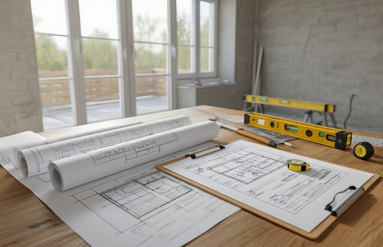
Before beginning any graphene underfloor heating installation, conducting a thorough assessment of room insulation and calculating precise heating requirements forms the foundation of a successful project. This critical first step determines the system’s effectiveness, energy efficiency, and overall performance throughout its operational life.
The heat loss calculation process requires careful evaluation of multiple factors that directly impact your graphene heating film system’s sizing and configuration. Room size serves as the primary factor, with larger spaces naturally requiring more heating capacity. However, surface area alone doesn’t tell the complete story – insulation quality plays an equally crucial role in determining actual heating demands.
Poor insulation significantly increases heat loss through walls, floors, windows, and ceilings, forcing your graphene heating system to work harder and consume more energy. When evaluating insulation quality, examine wall construction, window types, and existing floor insulation. Single-glazed windows create substantial heat loss compared to double or triple-glazed units, while solid walls without cavity insulation lose considerably more heat than modern insulated construction.
The calculation methodology involves assessing transmission losses through each building component. Each element – walls, windows, roof, and floor – has its own U-value measuring heat transfer efficiency. The basic formula for transmission losses uses: Heat Loss (W) = Area (m²) × U-value (W/m²K) × Temperature Difference (°C). This calculation must be performed separately for every building component to achieve accurate results.
Ventilation losses represent another significant factor in heat loss calculations. When heated indoor air gets replaced by cooler outdoor air through natural ventilation or mechanical systems, substantial energy losses occur. The ventilation loss calculation uses: Heat Loss (W) = Volume (m³) × Air Change Rate (1/hr) × Specific Heat Capacity (J/kg·K) × Temperature Difference (°C).
The air change rate indicates how frequently the building’s air volume gets completely replaced, varying significantly between older properties with natural ventilation and modern buildings with controlled mechanical ventilation systems. Older properties typically experience higher air change rates, increasing heating requirements accordingly.
Temperature differential between desired indoor conditions and expected outdoor temperatures directly affects heating demand. Greater temperature differences require higher heat output from your graphene heating film system. Consider both average winter temperatures and extreme cold periods in your area when calculating requirements.
Room usage patterns also influence heating requirements. Bedrooms typically need lower temperatures than living areas, while bathrooms often require higher comfort levels. Consider these usage variations when planning zone-specific heating capacities for your graphene underfloor heating system.
Choosing Between Heating Film Pads and Integrated Systems
Graphene underfloor heating technology offers two primary configuration options: heating film pads and integrated systems. Understanding the distinctions between these approaches enables informed decision-making based on your specific installation requirements and project constraints.
Heating film pads represent the more straightforward installation option, consisting of pre-manufactured graphene heating elements embedded in flexible film matrices. These pads come in standardized sizes and can be cut to fit specific room dimensions, making them particularly suitable for retrofit applications where minimal floor height increase is essential.
The primary advantage of heating film pads lies in their installation simplicity. These systems can be laid directly over existing floor surfaces including timber, concrete, stone, or tiles, minimizing disruption during installation. The thin profile of film pads typically adds only 2-3mm to floor height, making them ideal for situations where door clearances and floor transitions present challenges.
Film pad systems offer excellent flexibility in room layout planning. Individual pads can be positioned to avoid permanent fixtures like built-in furniture or kitchen islands, ensuring efficient heat distribution only where needed. This targeted approach can improve energy efficiency by avoiding heating unused floor areas.
However, film pad systems may have limitations in terms of maximum power output per square meter. While suitable for most residential applications, rooms with exceptionally high heat loss may require closer examination to ensure adequate heating capacity. The modular nature of film pads also means more electrical connections, potentially increasing installation complexity in larger spaces.
Integrated graphene heating systems represent a more comprehensive approach, incorporating graphene heating elements directly into purpose-built floor construction assemblies. These systems typically involve specialized subflooring materials with integrated heating elements, offering superior heat distribution and potentially higher power densities.
Integrated systems excel in new construction projects where floor build-up can be planned from the outset. They often provide more uniform heat distribution across the entire floor surface, eliminating potential temperature variations between pad edges and centers that might occur with individual film pads.
The installation process for integrated systems requires more substantial floor preparation but can deliver superior long-term performance. These systems often integrate better with smart home controls and can accommodate more sophisticated zoning arrangements for different areas within large spaces.
When choosing between these options, consider the installation environment carefully. Retrofit projects often favor film pad systems due to their minimal disruption and thin profile. New construction projects may benefit from integrated systems’ superior performance characteristics and seamless integration with modern building techniques.
Budget considerations also influence system selection. Film pad systems typically involve lower upfront costs but may require more complex electrical work for larger installations. Integrated systems often command higher initial investment but can provide better long-term value through improved efficiency and performance.
Required Tools and Materials for Installation
Successful graphene underfloor heating installation demands careful preparation of appropriate tools and materials before beginning work. Unlike traditional wet underfloor heating systems, graphene installations require specialized equipment suited to electrical heating systems and precise film handling.
Essential cutting tools form the foundation of any graphene heating film installation toolkit. Sharp scissors designed for cutting heating film materials ensure clean, precise edges that won’t damage heating elements. A quality craft knife with replaceable blades provides backup cutting capability and enables detailed trimming around obstacles. Wire cutters and wire strippers are necessary for electrical connections, with strippers capable of handling the specific wire gauges used in graphene heating systems.
Measuring tools ensure accurate installation and proper system sizing. A reliable tape measure, preferably 5 meters or longer, enables room dimension verification and heating film positioning. A straight edge or long ruler assists with marking cutting lines and ensuring film alignment during installation.
Electrical installation tools are crucial for safe, reliable connections. A multimeter capable of measuring resistance and continuity allows system testing throughout installation and commissioning. Screwdrivers in various sizes accommodate different electrical connection types, while a voltage tester ensures safe working conditions around electrical circuits.
Installation materials vary depending on the specific graphene heating system chosen, but several items are universally required. Joint tape designed for heating film systems secures film edges and creates weatherproof seals between adjacent film sections. This specialized tape maintains electrical insulation while providing mechanical protection for film edges.
Insulation materials play a critical role in system efficiency and performance. Reflective insulation boards designed for underfloor heating applications reflect heat upward into the room rather than allowing it to escape downward into the subfloor structure. These boards typically feature aluminum backing with foam or fiber insulation cores.
Floor sensors represent another essential component for proper system operation. These temperature sensors monitor actual floor temperature and provide feedback to the thermostat controller, ensuring safe operation within manufacturer specifications. Sensor conduit protects the sensor cable during installation and allows future replacement if necessary.
Electrical conduit and appropriate wiring enable safe connections between heating films and control systems. The conduit size must accommodate both power and sensor cables while meeting local electrical code requirements. Proper gauge electrical wire ensures adequate current carrying capacity for the total system load.
Leveling compounds may be necessary depending on existing floor conditions. Self-leveling compounds designed for use with electric underfloor heating systems can smooth minor floor irregularities and provide a suitable surface for film installation. These compounds must be compatible with heating systems and cure properly around electrical elements.
Adhesive materials secure heating films to substrate floors where necessary. Specialized adhesives designed for underfloor heating applications maintain their properties under temperature cycling and won’t interfere with heat transfer. Standard construction adhesives may not be suitable due to temperature sensitivity.
Protection materials safeguard installed heating films during subsequent construction activities. Protective sheeting prevents damage from foot traffic, tool drops, or construction debris during the period between heating system installation and final floor covering application.
Safety Precautions and Power Requirements
Electrical safety represents the paramount concern during graphene underfloor heating installation, requiring strict adherence to safety protocols and electrical codes throughout the project. The combination of electrical systems and floor-based installation creates specific hazards that demand careful attention and professional expertise.
Power requirements for graphene heating systems vary significantly based on room size, insulation quality, and desired heating capacity. Typical residential installations require 100-200 watts per square meter, though well-insulated spaces may need less while poorly insulated areas require more. This power density translates to specific electrical circuit requirements that must be planned before installation begins.
Electrical circuit planning requires professional evaluation to ensure adequate supply capacity. Most graphene heating systems operate on standard 240V circuits, but total amperage requirements depend on the heated area size. Large installations may require multiple circuits to avoid overloading any single electrical pathway. Circuit breaker sizing must match the total connected load with appropriate safety margins.
Ground Fault Circuit Interrupter (GFCI) protection is typically required for underfloor heating installations to prevent electrical shock hazards. These safety devices monitor electrical current flow and immediately disconnect power if ground faults are detected. GFCI protection must be properly sized for the heating system load and installed according to local electrical codes.
Professional electrical connections ensure safe, reliable system operation throughout its service life. While heating film installation may be within DIY capabilities, electrical connections to the main electrical panel should always be performed by qualified electricians. This professional involvement ensures code compliance and proper installation techniques.
Before beginning installation, electrical supply verification confirms adequate power availability for the planned heating system. Existing electrical panels may require upgrades to accommodate additional heating loads, particularly in older properties with limited electrical capacity. This assessment should occur early in the planning process to avoid delays during installation.
Working environment safety requires attention to typical construction hazards plus specific considerations for electrical work. Ensure adequate lighting throughout the work area and maintain clear pathways free from tools and materials. Dust control measures protect both workers and electrical components during installation.
Personal protective equipment appropriate for electrical work includes safety glasses, work gloves designed for electrical applications, and non-slip footwear. Avoid working in damp conditions and ensure all power sources are properly isolated before beginning electrical connections.
System testing protocols verify proper installation and safe operation before commissioning. Initial resistance measurements confirm heating film integrity, while insulation resistance testing ensures no short circuits exist between heating elements and ground. These tests should be performed at multiple stages during installation to identify problems early.
Documentation requirements include maintaining installation records, electrical connection diagrams, and system specifications for future reference. This documentation proves essential for warranty claims, troubleshooting, and future maintenance activities. Many manufacturers require proper documentation for warranty coverage.
Emergency procedures should be established before work begins, including identification of electrical disconnects and emergency contact information for electrical emergencies. All personnel involved in installation should understand these procedures and know how to safely respond to electrical incidents.
Power quality considerations ensure optimal system performance and longevity. Voltage fluctuations, electrical noise, and power factor issues can affect heating system operation. These factors are particularly important in older buildings or areas with unstable electrical supply conditions.
Installing Graphene Heating Film Systems
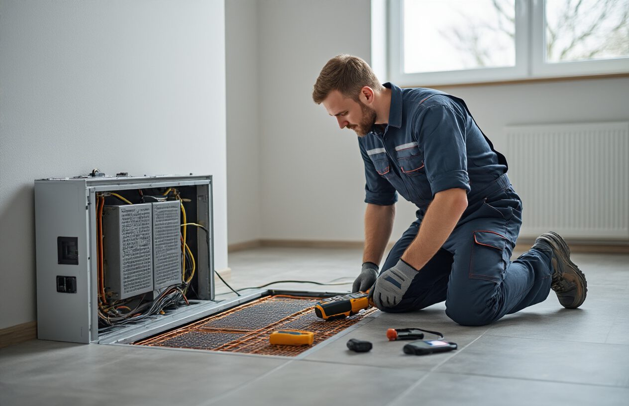
Preparing the Subfloor Surface
Now that you understand the benefits of graphene underfloor heating technology, the first critical step in your graphene underfloor heating installation is ensuring the subfloor surface is properly prepared. The success of your entire graphene heating film system depends on having a clean, level, and stable foundation.
Begin by thoroughly cleaning the subfloor surface of any debris, dust, or contaminants. Any particles left on the surface can create uneven areas that may lead to hot spots or damage to the heating films over time. Use a vacuum cleaner to remove all loose debris, followed by a damp cloth to eliminate any remaining dust particles. The surface must be completely dry before proceeding with the installation.
Inspect the subfloor for any irregularities, cracks, or protruding elements such as nails or screws. These imperfections can damage the delicate graphene heating films and compromise the system’s performance. Use appropriate filler materials to level out any dips or holes in the subfloor. Sand down any high spots to create a smooth, uniform surface. The subfloor should be level within 3mm over any 1-meter span to ensure optimal performance of your graphene floor heating system.
Check the subfloor’s structural integrity to ensure it can support both the heating system and the final flooring material. The surface should be firm and stable with no flex or movement when walked upon. Any loose boards or unstable areas must be secured before installation begins.
Verify that the subfloor material is compatible with radiant heating systems. Most plywood, OSB, and concrete subfloors work well with graphene heating films, but always check the manufacturer’s specifications for your specific heating system to ensure compatibility.
Laying Out and positioning Heating Films
With the subfloor properly prepared, you can now begin the precise process of laying out your graphene heating films. This stage requires careful planning and attention to detail to ensure even heat distribution throughout your space and optimal performance of your electric underfloor heating installation.
Start by creating a detailed layout plan for your room. Measure the entire floor area accurately and identify any permanent fixtures such as built-in cabinets, kitchen islands, or bathroom fixtures where heating films should not be installed. Graphene heating films should never be placed under permanent fixtures as this can cause overheating and system damage.
Calculate the required coverage area, keeping in mind that you typically need to cover 80-90% of the open floor space for optimal heating performance. This coverage ensures adequate heat distribution while avoiding areas where furniture or fixtures will be permanently placed.
When positioning the heating films, maintain proper spacing from walls and permanent fixtures. The reference content indicates that the graphene heating film installation process requires following manufacturer specifications for spacing, which typically ranges from 10-20cm from walls and permanent structures.
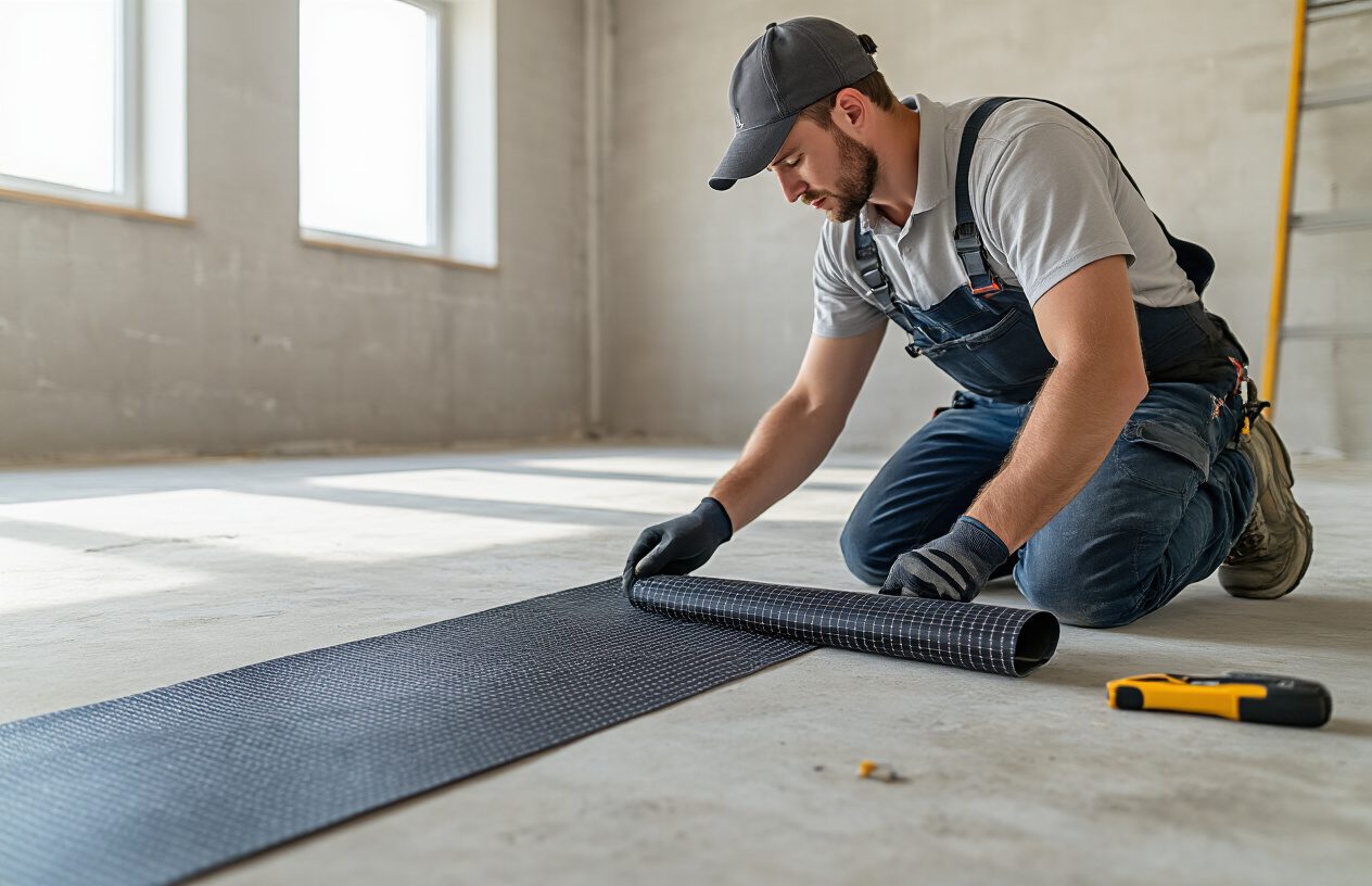
Roll out the heating films systematically, starting from one corner of the room and working methodically across the space. The films should lie completely flat against the subfloor surface without any wrinkles, bubbles, or overlapping areas. Each film strip should be positioned parallel to the others with consistent spacing between strips as specified by the manufacturer.
Pay special attention to the film orientation. The electrical connections on graphene heating films have specific directional requirements, and all films must be oriented correctly to ensure proper electrical connectivity. Mark the direction of electrical flow on your layout plan to maintain consistency throughout the installation.
Use the adhesive backing provided with the heating films to secure them to the subfloor. Remove the protective backing gradually as you position each film, ensuring complete adhesion without air bubbles. Apply firm, even pressure across the entire surface of each film to ensure proper bonding with the subfloor.
For rooms with irregular shapes or obstacles, you may need to cut heating films to fit. Use only the designated cutting lines marked on the films, and never cut through electrical elements. Most graphene heating films have specific cutting zones that allow for customization while maintaining electrical integrity.
Making Electrical Connections Safely
Previously, you’ve positioned your heating films correctly, and now the critical phase of making electrical connections begins. Safety is paramount during this stage of your how to install graphene heating film project, as improper electrical work can lead to system failure or dangerous conditions.
Before beginning any electrical work, ensure the main power supply to the installation area is completely disconnected. Use a multimeter to verify that no electrical current is present in the work area. This safety step is non-negotiable and must be completed before handling any electrical components.
Examine the connection points on your graphene heating films carefully. Each film will have designated connection areas where electrical leads attach. These connection points are specifically designed to handle the electrical load and must not be modified or bypassed.
Install the low-voltage transformer that powers your graphene heating system according to the manufacturer’s specifications. The reference content indicates that graphene heating films typically operate on low voltage, which requires a transformer to step down standard household voltage to the appropriate level for the heating films. Position the transformer in a readily accessible location that meets all electrical code requirements.
Connect the electrical leads from each heating film to the distribution network. Use only the connectors and materials specified by the manufacturer, as these components are designed to handle the specific electrical characteristics of graphene heating elements. Ensure all connections are secure and properly insulated to prevent short circuits or electrical failures.
Route all electrical cables carefully to avoid damage from foot traffic or installation of the final flooring. Use appropriate cable protection methods such as conduit or protective strips where cables cross high-traffic areas or where they might be subject to compression or abrasion.
Test each individual heating film connection before proceeding to the next installation phase. Use an appropriate multimeter to verify continuity and proper resistance values across each heating element. Document these readings for future reference and troubleshooting purposes.
Create a detailed wiring diagram showing the location of all heating films, electrical connections, and control circuits. This documentation will be invaluable for future maintenance, troubleshooting, or system modifications. Include information about circuit loads, transformer specifications, and thermostat connections in your documentation.
Ensure all electrical connections comply with local electrical codes and regulations. Many jurisdictions require electrical work to be performed or inspected by licensed electricians, particularly for permanent installations. Verify local requirements and obtain necessary permits before proceeding with electrical connections.
Installing Floor Sensors and Protection Layers
With electrical connections completed, the next crucial step involves installing floor sensors and protective layers that ensure optimal performance and longevity of your radiant floor heating graphene system. These components work together to provide accurate temperature monitoring and protect your investment from damage.
Install the floor temperature sensors in strategic locations throughout the heated area. These sensors provide critical feedback to the thermostat system, enabling precise temperature control and preventing overheating. Position sensors in representative areas that will accurately reflect the overall floor temperature, typically in the center of major heating zones.
The sensors should be installed in protective conduit to prevent damage during flooring installation and to allow for future replacement if necessary. Route the sensor cables back to the thermostat location using the same careful cable management techniques employed for the heating film connections.
Apply the specified insulation layer over the heating films and electrical connections. This layer serves multiple purposes: it provides electrical insulation, protects the heating films from mechanical damage during flooring installation, and helps ensure even heat distribution across the floor surface.
The thickness and type of insulation material must match the manufacturer’s specifications for your specific graphene heating system. Using incorrect insulation can lead to overheating, uneven temperature distribution, or system failure. The reference content emphasizes the importance of following manufacturer instructions precisely for safety and efficiency.
Install a vapor barrier if required by your specific installation conditions and flooring type. This barrier prevents moisture from reaching the heating films and electrical connections, which could cause system failure or safety hazards. The vapor barrier must be properly sealed at all seams and penetrations to maintain its effectiveness.
Add the thermal distribution layer that helps spread heat evenly across the floor surface and provides a stable base for the final flooring material. This layer is particularly important when installing tile or stone flooring, as it prevents point loading on the heating films while ensuring uniform heat transfer.
Ensure all protection layers are properly secured and will not shift during installation of the final flooring material. Any movement in these layers can create uneven areas that may damage the heating films or create performance issues.
Conduct a comprehensive system test before installing the final flooring material. This test should verify that all heating zones operate correctly, temperature sensors provide accurate readings, and the overall system responds properly to thermostat commands. Document all test results for future reference.
Install temporary protective covering over the entire system to prevent damage during installation of the final flooring. This covering should remain in place until all construction activities are complete and the system is ready for commissioning.
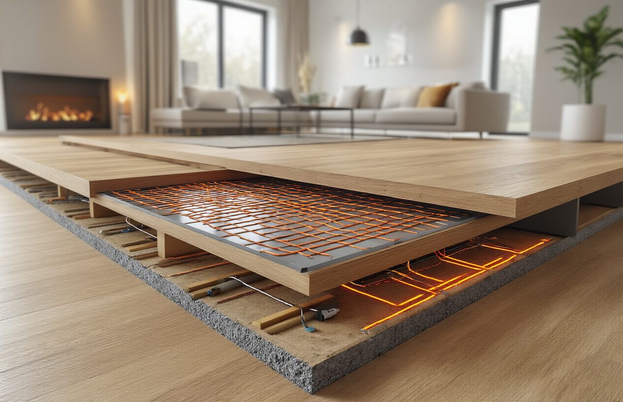
The reference content indicates that the heating film thickness is only 0.338cm, while integrated graphene underfloor heating systems have an overall thickness of about 2cm, which means these systems don’t significantly impact floor height compared to traditional water-based systems that typically require 8-10cm of additional floor height.
Verify that all system components are properly protected and that installation quality meets manufacturer standards before proceeding to thermostat installation and system commissioning. This attention to detail during the protection layer installation phase will ensure reliable operation and longevity of your graphene heating system for years to come.
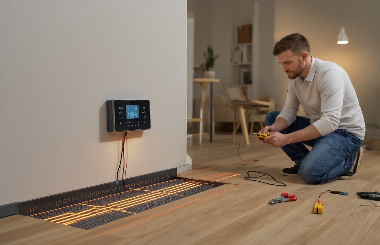
Setting Up Thermostat Controls
Positioning thermostats at optimal heights
Proper thermostat positioning is crucial for accurate temperature control and efficient operation of your graphene heating system thermostat. The optimal height for mounting underfloor heating thermostats ranges between 1.2 to 1.5 meters (4 to 5 feet) from the floor level. This positioning ensures the thermostat can accurately measure ambient air temperature while remaining easily accessible for daily operation.
When selecting the exact location on the wall, avoid areas that receive direct sunlight, as this can cause false readings and lead to inefficient heating cycles. Similarly, keep thermostats away from heat sources such as radiators, televisions, lamps, or areas near windows where drafts might affect temperature readings. Internal walls are generally preferred over external walls, as they provide more stable temperature conditions and reduce the influence of outdoor temperature fluctuations.
Consider the room’s air circulation patterns when positioning your thermostat. Areas with good natural air flow provide more representative temperature readings for the entire room. Avoid corners or areas where air tends to stagnate, as these locations may not reflect the true comfort level experienced in the main living areas of the room.
For rooms with high ceilings, maintain the standard mounting height rather than adjusting proportionally. The 1.2 to 1.5-meter range has been optimized for typical human activity levels and provides the most accurate representation of the temperature zone where occupants spend most of their time.
Wiring thermostat connections properly
Now that we have covered the optimal positioning, the next critical step involves establishing proper electrical connections for your graphene heating film setup. Understanding the wiring configuration is essential for safe and effective operation of your underfloor heating installation guide.
Most underfloor heating thermostats feature clearly labeled electrical terminals on the back of the unit. Before beginning any electrical work, ensure the power supply is completely isolated at the circuit breaker. This safety measure cannot be overstated when working with electric underfloor heating installation systems.
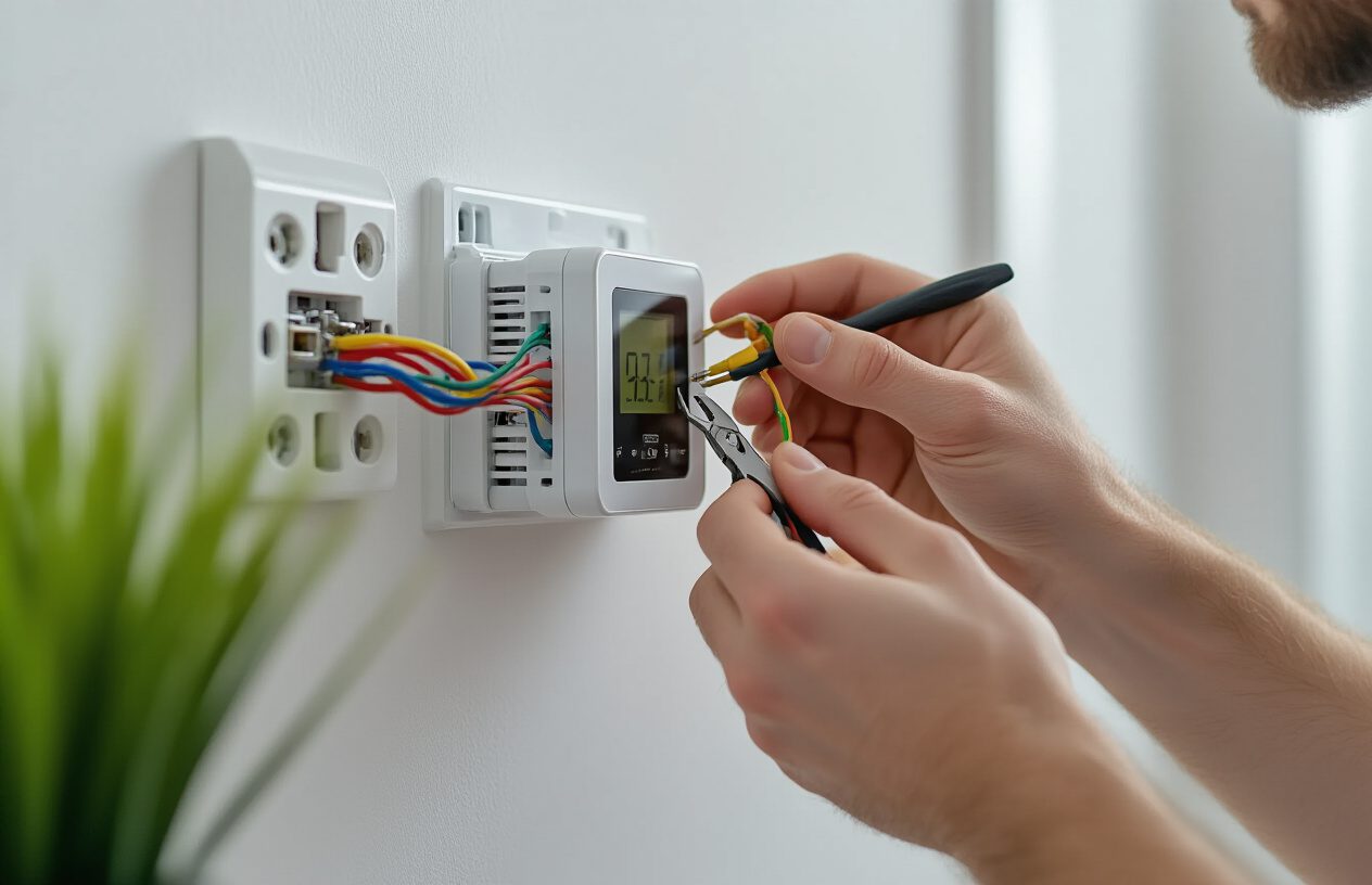
The typical wiring configuration involves four main wire connections: two for the line supply from your circuit breaker box and two for the load connections to your graphene heating film. For 120-volt systems, you’ll have a neutral wire and a hot line wire from the electrical panel. For 240-volt systems, both supply wires carry current and are considered “hot” lines.
The load connections are where your graphene floor heating system connects to the thermostat. These connections typically involve matching colors – red wires connect to red terminals, and black wires connect to black terminals. This color-coding system simplifies the installation process and reduces the likelihood of wiring errors.
Ground wire connections are equally important for safety. The ground wire from your graphene heating film must be connected to the ground wire in the electrical box where you’re mounting the thermostat. This grounding provides protection against electrical faults and ensures compliance with electrical safety codes.
When making wire connections, use appropriate wire nuts or terminal connectors rated for the current load of your system. Ensure all connections are tight and secure, as loose connections can cause arcing, overheating, and potential fire hazards. After completing all connections, carefully verify each connection against the wiring diagram provided with your thermostat.
Double-check your work by comparing the actual wiring in your installation with the manufacturer’s wiring diagram. This verification step is crucial for preventing operational issues and ensuring the longevity of your radiant floor heating graphene system.
Configuring temperature settings for each room
With the wiring connections properly established, configuring appropriate temperature settings becomes the next essential step in optimizing your graphene heating system performance. Different room types and usage patterns require tailored temperature configurations to achieve both comfort and energy efficiency.
Understanding the difference between floor temperature sensing and ambient air temperature sensing is fundamental to proper configuration. Floor temperature sensors monitor the actual temperature of the floor surface, while ambient sensors measure the air temperature in the room. Many modern thermostats offer dual sensing capabilities, providing both floor and air temperature monitoring simultaneously.
For rooms with different flooring materials, maximum temperature limits must be carefully observed. Soft floor finishes such as wood, carpet, and vinyl have a maximum recommended temperature of 27°C (80°F). Exceeding this temperature can cause damage to these materials, particularly vinyl flooring which can warp or discolor under excessive heat. Stone and tile surfaces can generally handle slightly higher temperatures but should still be monitored to prevent damage.
When using floor sensing mode exclusively, remember that floor temperatures typically run 6°C (11°F) higher than ambient air temperatures. This temperature differential means that setting your floor sensor to 23°C might result in a room air temperature of only 17°C, which may feel uncomfortably cool. Understanding this relationship is crucial for achieving desired comfort levels.
To determine optimal temperature settings for your specific space, follow a systematic approach. Begin by setting your thermostat to floor sensing mode and manual operation. Set the temperature to 25°C and allow the system to heat up for several hours. After this warm-up period, assess the comfort level in the room and adjust accordingly. If the temperature feels too warm, reduce the setting; if too cool, increase it gradually.
Once you’ve identified your ideal floor temperature setting, switch the thermostat to dual sensing mode (both floor and air sensing). This configuration provides the ambient temperature reading, which represents the actual comfort level you’ve established. This ambient temperature becomes your reference point for programming scheduled heating periods.
For ultimate efficiency and floor protection, always recommend using dual sensing mode. This configuration ensures the system maintains comfortable air temperatures while preventing floor temperatures from exceeding safe limits for your specific flooring material.
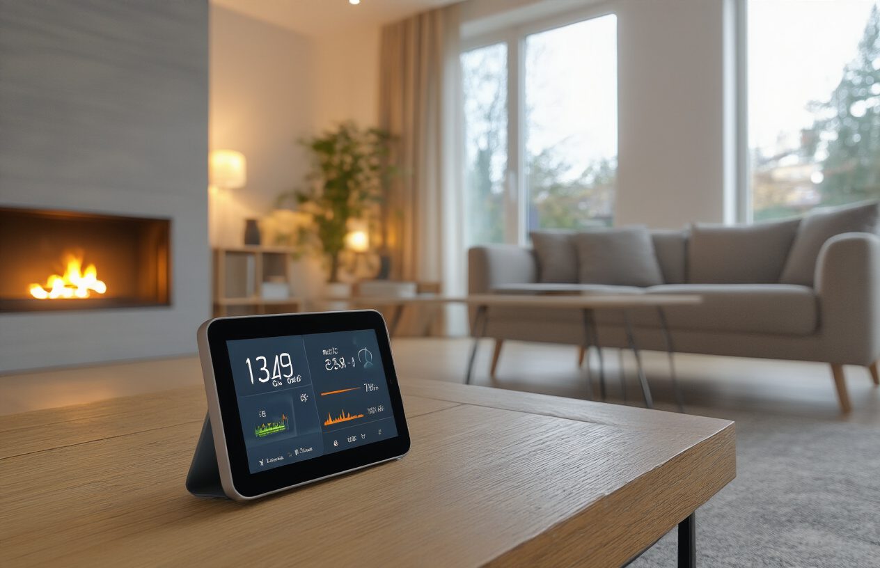
Programming energy-saving operation modes
Previously, we’ve established proper wiring and temperature settings; now we’ll explore advanced programming features that maximize energy efficiency while maintaining comfort. Modern programmable and smart thermostats offer sophisticated energy-saving operation modes that can significantly reduce heating costs when properly configured.
Setback temperatures form the foundation of energy-efficient operation. A setback temperature prevents your system from completely shutting down during unoccupied periods, instead maintaining a minimum temperature that reduces the energy required to reach target temperatures when heating resumes. For example, if your target comfort temperature is 23°C during occupied periods, setting a setback temperature of 17°C during away periods requires only a 6°C temperature increase when you return, compared to a potentially 13°C increase from a completely unheated space.
Smart adaptive start-up functions represent another significant energy-saving feature. These systems learn how long your specific graphene heating film system takes to reach target temperatures. By understanding this heating curve, the thermostat can begin heating cycles at precisely the right time to achieve your desired temperature when you need it, eliminating energy waste from starting too early or comfort loss from starting too late.
Open window detection technology automatically responds to sudden temperature drops caused by open doors or windows. When detected, the system temporarily suspends heating for approximately 15 minutes before resuming normal operation. This feature prevents energy waste during brief ventilation periods while ensuring comfort is quickly restored when normal conditions return.
Weather compensation features, available in smart thermostats, use real-time weather data to adjust heating schedules automatically. On warmer days, the system reduces heating output by a few degrees, maintaining comfort while optimizing energy consumption. This dynamic adjustment responds to changing outdoor conditions without requiring manual intervention.
Geolocation capabilities provide automated heating control based on occupancy. By setting a radius perimeter around your home, the system automatically enables heating when you’re within the designated area and disables it when you leave. This feature eliminates energy waste from accidentally leaving heating on when away from home.
Programming weekly heating schedules tailored to your lifestyle patterns maximizes both comfort and efficiency. Consider your daily routines when creating schedules – heating living areas during evening hours, bedrooms during sleeping periods, and reducing temperatures during work hours. A typical efficient schedule might include heating to 22°C from 6 AM to 9 AM, maintaining 18°C setback temperature until 5 PM, then resuming 22°C comfort temperatures until 10 PM.
Bluetooth connectivity options, such as those found in BT21 thermostats, provide smartphone control within a 10-15 meter range without requiring Wi-Fi connectivity. This feature offers convenient control while maintaining simplicity in setup and operation.
For dual control thermostats, programming separate schedules for floor heating and additional appliances like towel bars or mirror demisters adds another layer of efficiency. Independent control of these systems ensures each operates only when needed, further optimizing energy consumption.
Zone-based control programming allows different rooms to operate on independent schedules, accommodating varying usage patterns throughout your home. Bedrooms might heat primarily during sleeping hours, while living areas focus on evening comfort periods. This targeted approach eliminates waste from heating unused spaces.
Regular schedule review and adjustment ensure continued efficiency as seasonal conditions and lifestyle patterns change. What works efficiently in winter may require modification for spring and fall shoulder seasons when heating demands vary significantly.
First-Time System Activation
Initial power-up procedures at 18°C
Now that your graphene heating film system has been properly installed and connected to the thermostat controls, the first-time system activation requires careful attention to specific temperature protocols. The initial power-up procedure is crucial for ensuring optimal performance and preventing potential damage to your graphene underfloor heating installation.
Before activating your graphene heating film system for the first time, ensure that the ambient room temperature is maintained at a minimum of 18°C (64°F). This baseline temperature requirement is essential for proper system initialization and helps prevent thermal shock to the graphene heating elements. The room should be adequately insulated and protected from drafts during this initial activation phase.
Start the system activation process by setting your thermostat to exactly 18°C, regardless of the current ambient temperature. This conservative starting point allows the graphene heating film to gradually acclimate to electrical current flow while minimizing stress on the heating elements. Unlike traditional water-based underfloor heating systems that require complex manifold adjustments, graphene heating film systems offer more straightforward activation procedures through direct electrical control.
During the initial 24-hour period at 18°C, monitor the system closely for any unusual sounds, odors, or visual indicators that might suggest improper installation or connection issues. The graphene heating film should begin warming evenly across all installed areas within the first hour of activation. Pay particular attention to junction points and connection areas where electrical issues are most likely to manifest.
It’s important to note that graphene heating film systems respond much faster than traditional hydronic systems, typically reaching target temperatures within 15-30 minutes rather than the hours required for water-based systems. However, maintaining the initial 18°C setting for the full 24-hour period allows for complete system stabilization and ensures that all components are functioning harmoniously.
Running continuous operation tests
With the initial 18°C activation period complete, the next phase involves implementing a systematic continuous operation testing protocol. This testing phase is critical for verifying that your graphene underfloor heating installation can maintain consistent performance over extended periods without interruption or degradation.
Begin the continuous operation test by gradually increasing the thermostat setting by 1°C increments every 24 hours, following a methodical approach similar to traditional underfloor heating startup protocols. This gradual temperature increase allows you to monitor system performance at each temperature level while identifying any potential issues before they become problematic.
Day 1: Maintain 19°C (66°F) for 24 hours, observing heating uniformity across all zones
Day 2: Increase to 20°C (68°F) and monitor for consistent temperature maintenance
Day 3: Progress to 21°C (70°F), checking for any hot spots or cold areas
Day 4: Continue to 22°C (72°F), verifying proper thermostat response
Day 5: Advance to 23°C (73°F), ensuring energy consumption remains within expected parameters
Continue this pattern up to your desired maximum operating temperature, typically not exceeding 27°C (81°F) for floor surface temperatures to prevent damage to flooring materials and ensure user comfort. This systematic approach allows you to identify the optimal operating temperature for your specific installation while ensuring the system can maintain continuous operation without issues.
During each 24-hour testing period, document the time required for the system to reach the target temperature, the consistency of temperature maintenance, and any fluctuations in performance. Modern graphene heating film systems should demonstrate remarkably stable performance with minimal temperature variation once the target is reached.
Monitor electrical consumption throughout the continuous operation test to establish baseline energy usage patterns. This data will prove invaluable for future energy management and will help identify any efficiency issues early in the system’s operational life. Record peak consumption periods and steady-state consumption levels to understand the system’s energy characteristics fully.
Checking for proper system functionality
Previously established continuous operation data provides the foundation for comprehensive system functionality verification. This critical phase involves systematic testing of all system components to ensure optimal performance and identify any potential issues before regular operation begins.
Temperature uniformity testing represents the first key functionality check for your graphene heating film installation. Using an infrared thermometer or thermal imaging camera, measure floor surface temperatures across multiple points in each heated zone. Properly functioning graphene heating film systems should demonstrate temperature variations of no more than 2-3°C across the entire heated area. Significant temperature variations may indicate installation issues, damaged heating elements, or inadequate electrical connections.
Thermostat response testing ensures that your control system accurately maintains desired temperatures and responds appropriately to setting changes. Set the thermostat to various temperatures and measure the time required for the system to respond and reach the new target temperature. Graphene heating film systems typically respond within 15-30 minutes to thermostat adjustments, significantly faster than traditional hydronic systems.
Electrical safety verification involves checking all connections, junction boxes, and control components for proper installation and secure connections. Use a multimeter to verify voltage levels at key connection points and ensure that electrical consumption matches manufacturer specifications. Any unusual electrical readings or consumption patterns may indicate wiring issues or component problems that require immediate attention.
Zone control functionality, if applicable to your installation, requires testing each independently controlled area to verify proper operation. Each zone should heat and cool independently without affecting other areas, and the control system should accurately maintain different temperatures in different zones when required.
Ground fault circuit interrupter (GFCI) testing ensures electrical safety protection is functioning correctly. Test all GFCI devices protecting the graphene heating film circuits by pressing the test button and verifying that power is interrupted to the heating system. Reset the GFCI and confirm that power is restored and the system resumes normal operation.
Eliminating cold radiation from walls and floors
With proper system functionality verified, attention turns to addressing cold radiation issues that can significantly impact comfort and system efficiency. Cold radiation occurs when heat is lost to cold surfaces such as exterior walls, uninsulated floors, or thermal bridges, creating uncomfortable conditions despite adequate heating.
Cold radiation from exterior walls represents one of the most common comfort issues in heated spaces. Even with properly functioning graphene underfloor heating, cold exterior walls can create uncomfortable conditions through radiant heat loss from occupants to these cold surfaces. The heated floor provides warmth from below, but cold walls draw heat away from people, creating an unbalanced thermal environment.
To minimize wall-related cold radiation, ensure adequate wall insulation is in place, particularly on exterior walls. Thermal bridging through structural elements can create cold spots that draw heat away from the space despite adequate floor heating. Consider supplementary heating near large windows or thermal bridges if cold radiation remains problematic after graphene heating film activation.
Floor-related cold radiation can occur if insulation beneath the graphene heating film is inadequate or if thermal bridging allows heat to escape downward rather than radiating into the living space. During the functionality testing phase, use thermal imaging to identify any areas where heat may be escaping downward, indicating insulation deficiencies or thermal bridge issues.
Perimeter heat loss represents another source of cold radiation that can undermine graphene heating film effectiveness. Edge insulation around the heated area prevents lateral heat loss and ensures that generated heat radiates upward into the living space rather than escaping through adjacent unheated areas.
Air infiltration can create cold spots and drafts that contribute to cold radiation effects. Seal any air leaks around windows, doors, or other openings that might allow cold air infiltration. Even small air leaks can create localized cold spots that undermine the comfort provided by radiant floor heating.
Humidity control plays a crucial role in eliminating perceived cold radiation. Proper humidity levels enhance comfort and reduce the sensation of coldness from surfaces. Graphene heating film systems typically provide gentle, even heating that doesn’t excessively dry indoor air, but monitoring humidity levels ensures optimal comfort conditions.
Window treatments can significantly impact cold radiation from glazed surfaces. Insulating window coverings reduce radiant heat loss to cold glass surfaces, improving overall comfort and reducing the load on your graphene heating film system. Consider cellular shades, heavy curtains, or other insulating treatments for large windows or sliding glass doors.
Furniture placement affects heat distribution and can contribute to cold spots if large pieces block radiant heat flow. Arrange furniture to allow proper heat circulation while avoiding placement directly against cold exterior walls where cold radiation effects are most pronounced.
By systematically addressing these cold radiation sources during first-time system activation, you establish optimal conditions for your graphene underfloor heating installation to provide consistent, comfortable heating throughout the heated space.
Daily Operation and Energy Management
Optimal Temperature Settings for Comfort and Efficiency
Now that your graphene underfloor heating system is activated and operational, achieving the perfect balance between comfort and energy efficiency becomes crucial. Graphene heating film systems operate most effectively at lower temperatures compared to traditional radiator systems, making them inherently more energy-efficient while providing superior comfort.
The optimal room temperature for most living spaces ranges between 18-21°C (64-70°F), with graphene underfloor heating systems excelling in this range due to their radiant heat distribution properties. Unlike conventional heating systems that rely on convection, your graphene heating film creates a uniform temperature profile across the floor surface, eliminating cold spots and providing consistent warmth throughout the room.
For different areas of your home, consider these temperature recommendations to maximize both comfort and efficiency:
- Living rooms and bedrooms: 19-21°C (66-70°F)
- Bathrooms: 22-24°C (72-75°F)
- Kitchens: 18-20°C (64-68°F)
- Hallways and corridors: 16-18°C (61-64°F)
The energy efficiency of your graphene underfloor heating system is significantly enhanced when operating at these lower temperatures. Traditional radiator systems typically require water temperatures of 70-80°C, while graphene heating film operates effectively at much lower surface temperatures, resulting in 15-40% less energy consumption.
Understanding your floor finish is essential for optimal temperature management. Stone and tile floors have excellent heat conductivity but take longer to heat up initially, while maintaining heat for extended periods. Engineered wood floors heat up more quickly but may not retain heat as long. This thermal mass characteristic should influence your temperature settings and heating schedules.
The radiant heat distribution from graphene heating film systems heats objects and surfaces within the room rather than just the air, creating a more comfortable environment at lower ambient temperatures. This phenomenon allows you to maintain comfort while setting your thermostat 2-3°C lower than you would with traditional heating systems, resulting in substantial energy savings.
Managing Heating During Short and Long Absences
Previously, we’ve established the optimal temperature settings for daily use. With this in mind, next we’ll explore how to effectively manage your graphene underfloor heating system during various absence periods to maximize energy efficiency without compromising comfort upon your return.
Short Absences (1-8 Hours)
For short absences such as work days or brief outings, the most efficient approach depends on your floor type and insulation quality. With proper floor insulation, which can increase efficiency by up to 50%, your graphene heating system can maintain comfortable temperatures with minimal energy waste.
During short absences, consider reducing the temperature by 3-5°C rather than turning the system off completely. This approach is particularly effective because:
- Graphene heating film systems respond quickly to temperature changes
- The thermal mass of your floor continues to provide radiant heat
- Energy consumption for reheating is minimized upon your return
- System longevity is improved through consistent operation rather than frequent on/off cycles
For rooms with good insulation and concrete substrates, which have better heat retention than timber substrates, you can safely reduce temperatures for up to 8 hours with quick recovery times.
Long Absences (1-7 Days)
For extended absences, such as vacations or business trips, more significant temperature reductions are appropriate. Set your thermostat to maintain minimum temperatures of:
- Occupied homes with residents: 12-15°C (54-59°F)
- Completely vacant properties: 7-10°C (45-50°F) to prevent freezing and moisture issues
The 100% efficiency of electric underfloor heating at point of use means every unit of electricity is converted to heat, making these setback temperatures economically viable for maintaining basic comfort levels.
When planning your return, utilize programmable or smart thermostats to begin warming your home 2-4 hours before arrival. The quick response time of graphene heating film allows for rapid temperature recovery compared to traditional heating systems.
Zonal Management Strategies
Implementing zonal heating control provides the ultimate efficiency during absences. Rather than heating your entire home, focus on essential areas:
- Maintain higher temperatures in frequently used rooms upon return
- Reduce temperatures significantly in guest rooms and storage areas
- Keep bathroom temperatures slightly elevated for comfort and humidity control
This zonal approach can reduce overall energy consumption by ensuring heating is only provided where and when needed, rather than heating the whole house simultaneously.
Utilizing Peak and Valley Electricity Pricing
With smart energy management becoming increasingly important, understanding how to leverage electricity pricing structures can significantly impact your graphene underfloor heating operating costs. Many utility companies offer time-of-use pricing with distinct peak and off-peak rates.
Understanding Peak and Off-Peak Periods
Typically, electricity pricing follows these patterns:
- Peak hours: 4 PM – 9 PM (highest rates)
- Off-peak hours: 11 PM – 7 AM (lowest rates)
- Standard hours: All other times (mid-range rates)
Your graphene heating film system’s thermal mass characteristics make it ideally suited for peak-shaving strategies. By heating your floors during off-peak hours, you can store thermal energy that continues to provide comfort during peak pricing periods.
Pre-Heating Strategies
During off-peak hours, you can raise your floor temperature 2-3°C above normal settings. The radiant heat stored in your floor finish and substrate will continue providing warmth for several hours, allowing you to reduce or turn off heating during peak pricing periods.
This strategy is particularly effective with:
- Stone and tile floors that retain heat longer
- Well-insulated floors that minimize heat loss to substrates
- Rooms with minimal heat loss through windows and walls
Smart Thermostat Programming for Rate Optimization
Modern programmable and smart thermostats can be configured to automatically optimize heating schedules based on electricity pricing. Consider these programming strategies:
Off-Peak Charging (11 PM – 7 AM)
- Increase temperature by 2-3°C above comfort settings
- Focus on rooms that will be used first in the morning
- Maximize thermal storage in high thermal mass floors
Peak Avoidance (4 PM – 9 PM)
- Reduce temperature by 3-4°C in unoccupied rooms
- Maintain minimal heating in occupied spaces
- Rely on stored thermal energy from off-peak charging
Transition Periods
- Gradually adjust temperatures during standard rate periods
- Prepare floors for peak avoidance or off-peak charging
- Monitor comfort levels and adjust strategies accordingly
Nighttime Temperature Adjustment Strategies
Now that we’ve covered daily operation principles, implementing effective nighttime temperature management becomes crucial for both energy efficiency and sleep comfort. Graphene underfloor heating systems excel in creating optimal sleeping environments through precise temperature control.
Optimal Sleeping Temperatures
Research indicates that optimal sleeping temperatures range from 15-19°C (59-66°F), significantly lower than daytime comfort levels. Your graphene heating system’s precise temperature control allows for gradual temperature reductions that promote better sleep quality while maximizing energy savings.
Gradual Temperature Reduction Protocol
Rather than abrupt temperature changes that can cause discomfort, implement gradual reductions:
- 9 PM: Begin reducing temperature by 1-2°C from evening settings
- 10 PM: Further reduce by another 1-2°C
- 11 PM: Achieve target nighttime temperature of 16-18°C
- 6 AM: Begin gradual warming for morning comfort
This gradual approach leverages the thermal mass of your floor system, providing consistent radiant heat even as air temperatures decrease.
Bedroom-Specific Considerations
Different bedrooms may require unique nighttime strategies based on:
Master Bedrooms
- Maintain slightly higher temperatures (17-19°C) for adult comfort
- Consider individual preferences and bedding insulation
- Coordinate with partner’s temperature preferences
Children’s Rooms
- Maintain consistent temperatures around 18-20°C
- Avoid significant nighttime reductions that might cause discomfort
- Monitor room humidity levels alongside temperature
Guest Bedrooms
- Reduce to minimal temperatures (12-15°C) when unoccupied
- Program warming cycles before guest arrivals
- Maintain basic heating to prevent humidity and comfort issues
Integration with Sleep Cycle Optimization
Advanced smart thermostats can integrate with sleep tracking devices to optimize heating schedules based on actual sleep patterns. This integration allows for:
- Temperature reductions during deep sleep phases
- Gentle warming during natural wake cycles
- Personalized heating schedules based on individual sleep patterns
Morning Warm-Up Strategies
The quick response time of graphene heating film systems enables efficient morning warm-up routines. Begin warming your bedroom and bathroom 30-60 minutes before your typical wake time to ensure comfort without wasting energy during peak sleep hours.
Consider staggered warm-up schedules for different areas:
- Bathrooms: Begin warming 45 minutes before wake time for immediate comfort
- Bedrooms: Gentle warming 30 minutes before wake time
- Kitchen/Dining: Coordinate with breakfast preparation timing
Energy Savings Through Nighttime Management
Effective nighttime temperature management can reduce overall heating costs by 8-15% while improving sleep quality. The radiant heat characteristics of graphene systems maintain comfort even with lower air temperatures, making these strategies more effective than with traditional heating systems.
The combination of lower nighttime temperatures, off-peak electricity rates, and the thermal storage capabilities of your floor system creates optimal conditions for energy-efficient operation. By storing thermal energy during low-rate periods and allowing gradual temperature reductions during sleep hours, you maximize both comfort and efficiency throughout your daily heating cycle.
Regular monitoring of your energy consumption patterns will help you fine-tune these strategies based on your specific home characteristics, lifestyle, and local utility rate structures. The inherent efficiency of graphene underfloor heating systems, combined with thoughtful operational strategies, ensures optimal comfort while minimizing environmental impact and operating costs.
Maintenance and Troubleshooting
Protecting the System from Water Damage
Now that you have successfully installed your graphene underfloor heating system, protecting it from water damage becomes a critical maintenance priority. Graphene heating films, despite their remarkable durability and chemical stability, require careful protection from moisture intrusion to maintain optimal performance and longevity.
Water damage represents one of the most serious threats to any electrical heating system, and graphene underfloor heating is no exception. The unique properties of graphene that make it an excellent heating material – including its superior thermal conductivity and electrical efficiency – can be compromised when exposed to moisture. Understanding how to prevent water damage is essential for maintaining your system’s performance and avoiding costly repairs.
The primary vulnerability points in your graphene heating system include connection joints, thermostat wiring, and areas where the heating film meets flooring transitions. These locations require special attention during both initial installation and ongoing maintenance. Regular inspection of these critical areas should become part of your routine maintenance schedule.
When installing flooring over your graphene heating film, ensure that any adhesives, grouts, or sealants used are completely cured and moisture-resistant. Moisture trapped beneath flooring materials can create condensation that gradually works its way to the heating elements. This is particularly important in bathrooms, kitchens, and other high-humidity areas where graphene heating systems are commonly installed.
Implement a comprehensive moisture barrier system during installation. This includes using appropriate vapor barriers beneath the heating film and ensuring all seams are properly sealed. The vapor barrier serves as the first line of defense against moisture migration from the subfloor, which could otherwise reach the graphene heating elements over time.
For areas prone to water exposure, consider installing water detection sensors near your graphene heating system. These sensors can provide early warning of moisture intrusion, allowing you to address potential issues before they cause significant damage to your heating elements. Modern water detection systems can be integrated with your home automation system to provide immediate alerts via smartphone notifications.
Regular inspection of plumbing fixtures above or near your graphene heating installation is crucial. Even minor leaks from pipes, fixtures, or appliances can gradually compromise your heating system. Establish a routine inspection schedule that includes checking for signs of water stains, unusual odors, or soft spots in flooring that might indicate moisture problems.
Avoiding Damage from Sharp Objects or Heavy Coverings
Previously, I’ve emphasized the importance of protecting your graphene heating film during installation, but ongoing protection from physical damage is equally critical for long-term system performance. The thin profile of graphene heating films, while advantageous for installation flexibility, requires careful consideration of what materials and objects come into contact with the heated floor surface.
Sharp objects represent a significant threat to graphene heating film integrity. Common household items such as furniture legs, high heels, pet claws, and dropped kitchen utensils can potentially puncture or damage the heating elements. While graphene itself is remarkably strong – stronger than steel by weight – the thin film format used in heating applications requires protection from concentrated point loads and sharp impacts.
When moving furniture across floors with graphene heating systems, always use furniture pads or sliders to distribute weight and prevent damage. Avoid dragging heavy items directly across the floor surface, as this can create tears or punctures in the heating film beneath the flooring material. For permanent furniture placement, consider using furniture cups or protective mats that distribute weight over a larger area.
The choice of flooring material over your graphene heating system significantly impacts protection from physical damage. Hard flooring materials like ceramic tile, stone, or engineered hardwood provide excellent protection for the heating film underneath. However, ensure that any underlayment materials used are compatible with radiant heating and won’t degrade under thermal cycling.
Carpet installations over graphene heating require special consideration for pad selection and carpet attachment methods. Avoid carpet padding with sharp or hard backing materials that could damage the heating film. Similarly, ensure that carpet tack strips are positioned to avoid the heating elements, and use appropriate fastening methods that don’t penetrate the heating film layer.
Heavy coverings and thick rugs can significantly impact your graphene heating system’s performance by creating insulation layers that trap heat. This thermal blanket effect can cause the heating elements to work harder to maintain desired temperatures, potentially leading to overheating and premature system failure. The superior thermal conductivity of graphene works best when heat can transfer efficiently to the room air.
Establish guidelines for area rug and furniture placement that consider both protection and performance. Large, thick rugs should be avoided over heated areas, as they can create hot spots and reduce overall system efficiency. If decorative rugs are desired, choose thin, breathable materials that allow heat transfer while providing minimal thermal resistance.
For commercial installations or high-traffic areas, consider implementing protective measures such as walk-off mats at entrances to reduce the introduction of debris and sharp objects. Regular maintenance of these protective elements helps ensure they continue to serve their intended purpose of protecting your graphene heating investment.
Identifying Common Thermostat Issues and Solutions
With this in mind, next, we’ll examine the thermostat control system, which serves as the brain of your graphene underfloor heating installation. Thermostat issues are among the most common problems encountered with heating systems, yet they are often the most straightforward to diagnose and resolve. Understanding how to identify and address these issues can save significant time and expense while maintaining optimal system performance.
Temperature inconsistencies represent the most frequent thermostat-related complaint. If your graphene heating system fails to maintain consistent temperatures or seems to cycle on and off frequently, the thermostat calibration may have drifted over time. Modern programmable thermostats typically include calibration adjustment features that allow fine-tuning of temperature readings to match actual room conditions.
To verify thermostat accuracy, use an independent, calibrated thermometer placed near the thermostat location. Compare readings over several hours and different temperature settings. If consistent discrepancies exist, most thermostats allow calibration adjustments through their programming menus. Consult your thermostat manual for specific calibration procedures, as these vary between manufacturers and models.
Power-related issues often manifest as complete system non-operation or intermittent functionality. Begin troubleshooting by verifying that the thermostat display is functioning normally. A blank or dim display may indicate power supply problems, low battery conditions (for battery-powered units), or internal component failure. Check circuit breakers and fuses associated with both the thermostat and heating system to ensure proper electrical supply.
For smart thermostats connected to your home Wi-Fi network, connectivity issues can appear as system malfunctions. Loss of network connection may prevent remote operation or cause the thermostat to revert to default programming. Check your home network status and verify that the thermostat maintains proper Wi-Fi connection. Many smart thermostats include network diagnostic features accessible through their setup menus.
Programming errors account for numerous perceived thermostat malfunctions. Inadvertent schedule changes, incorrect time settings, or activation of energy-saving modes can result in unexpected system behavior. Review your thermostat programming periodically to ensure schedules align with your current needs and that all settings remain as intended.
Sensor placement and environmental factors significantly impact thermostat performance. Thermostats located near heat sources, in direct sunlight, or in areas with poor air circulation may provide inaccurate temperature readings. Similarly, sensors blocked by furniture or decorations cannot accurately measure room conditions. Ensure thermostat sensors have unobstructed airflow and are positioned away from external heat sources.
Floor sensor issues specific to radiant heating systems require special attention. Many graphene heating system thermostats include both air and floor temperature sensors to optimize comfort and energy efficiency. Floor sensors can become damaged during flooring installation or maintenance activities. If your system exhibits floor temperature irregularities while air temperature control remains normal, the floor sensor may require inspection or replacement.
Advanced diagnostic features available on modern thermostats can help identify system issues before they become major problems. Many units include operational logs, error codes, and performance monitoring capabilities. Familiarize yourself with these diagnostic tools and review them regularly to identify developing trends or issues that may require attention.
Recognizing When to Contact Professional Repair Services
Understanding the limits of DIY maintenance and recognizing when professional intervention becomes necessary is crucial for both safety and system longevity. While many graphene heating system issues can be addressed through basic troubleshooting and maintenance, certain situations require the expertise and specialized equipment that only qualified professionals possess.
Electrical issues present the most critical safety concern and should always prompt immediate professional consultation. Signs of electrical problems include flickering lights when the heating system operates, unusual odors suggesting overheating components, visible sparking or arcing, or circuit breakers that trip repeatedly when the system activates. These symptoms indicate potential safety hazards that require immediate attention from qualified electrical contractors familiar with radiant heating systems.
Significant performance degradation across large areas of your heating system typically indicates problems beyond simple maintenance or minor adjustments. If multiple zones fail to heat properly, if energy consumption increases dramatically without corresponding temperature improvement, or if the system requires increasingly frequent thermostat adjustments to maintain comfort, comprehensive professional evaluation becomes necessary.
Water damage assessment and remediation require professional expertise to fully evaluate the extent of damage and determine appropriate repair strategies. While minor moisture exposure might be addressed through DIY methods, significant water intrusion can compromise heating elements, electrical connections, and structural components in ways that aren’t immediately apparent. Professional water damage specialists have the equipment and experience necessary to assess hidden damage and implement appropriate remediation strategies.
Complex diagnostic requirements beyond basic troubleshooting indicate the need for professional service. Modern graphene heating systems include sophisticated control systems and monitoring capabilities that may require specialized diagnostic equipment for proper evaluation. If basic troubleshooting steps fail to identify or resolve performance issues, professional technicians with system-specific training and diagnostic tools can provide comprehensive system analysis.
Warranty considerations often require professional service to maintain coverage. Many graphene heating system warranties specify that repairs and modifications must be performed by qualified professionals to remain valid. Attempting DIY repairs on warranty-covered systems may void coverage and result in significant out-of-pocket expenses for future issues. Review your system warranty terms to understand professional service requirements.
Safety concerns related to high-voltage electrical work necessitate professional intervention. Graphene heating systems operate at voltages that can cause serious injury or death if handled improperly. Any work involving electrical connections, control panels, or system modifications should be performed only by licensed electricians with radiant heating system experience.
When contacting professional services, provide comprehensive information about observed symptoms, recent changes to the system or environment, and any troubleshooting steps already attempted. This information helps professionals prepare appropriately for service calls and can reduce diagnostic time and costs. Document system performance issues with photographs, temperature readings, and operational logs when possible to assist professional evaluation.
Establish relationships with qualified professionals before problems occur. Identify local contractors with specific graphene heating system experience and maintain their contact information for emergency situations. Many contractors offer preventive maintenance services that can identify potential issues before they become major problems, ultimately saving money and preventing system failures.
Professional maintenance schedules vary based on system complexity, usage patterns, and environmental conditions. Generally, annual professional inspections provide optimal balance between maintenance costs and system reliability. However, commercial installations or systems in challenging environments may benefit from more frequent professional attention to ensure optimal performance and longevity.
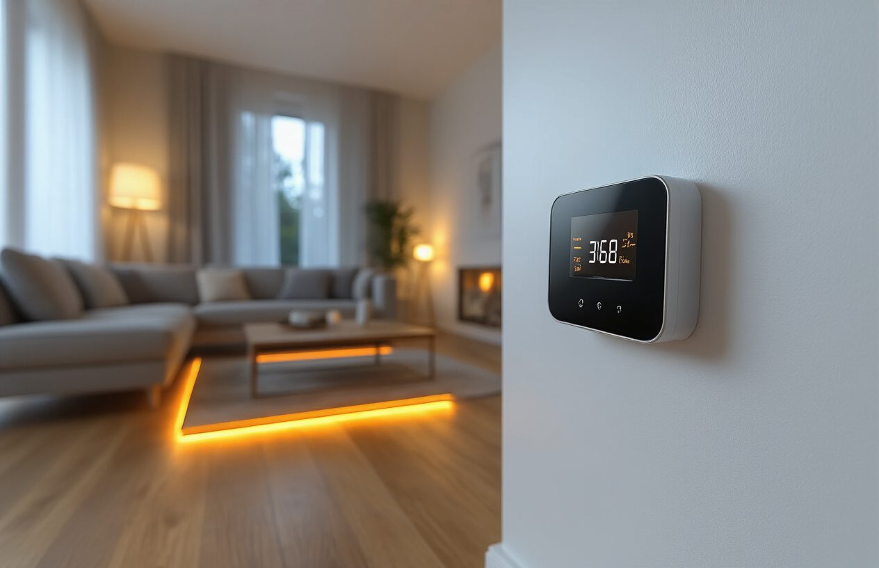
Installing graphene underfloor heating represents a smart investment in modern home comfort and energy efficiency. By following the step-by-step process outlined in this guide—from understanding the technology and pre-installation planning to proper system activation and daily operation—you’ll achieve a reliable heating solution that delivers consistent warmth throughout your home. The thin profile of graphene heating films (only 0.338cm thick) preserves valuable floor height while providing rapid heating that can reach comfortable temperatures within 15 minutes to an hour.
The long-term benefits of graphene underfloor heating make it an excellent choice for homeowners seeking maintenance-free operation. With a service life of 30-50 years and no required maintenance beyond basic thermostat operation, this system offers significant advantages over traditional heating methods. Remember to maintain proper insulation, avoid covering large areas with poor heat-conducting materials, and follow the recommended temperature settings of 18-20°C for optimal energy efficiency. Should any issues arise, refer to the troubleshooting guidelines and contact professional technicians when necessary to ensure your system continues operating safely and effectively for decades to come.


